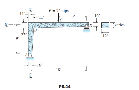
Computer study—Influence of supports on frame behavior.
(a) Using the RISA-2D computer program, compute the initial elastic deflection at midspan of
the girder in Figure P8.44, given that the support at D is a roller. For the computer analysis,
replace the tapered members by 3-ft-long segments of constant depth whose properties are
based on each segment’s midspan dimensions; that is, there will be 9 members and 10 joints.
When you set up the problem, specify in GLOBAL that forces are to be computed at three
sections. This will produce values of forces at both ends and at the center of each segment.
To account for cracking of the reinforced concrete, assume for girder BCD that I e = 0.35I G ; for
column AB assume I e = 0.7I G (compression forces in columns reduce cracking). Since
deflections of beams and one-story rigid frames are due almost entirely to moment and not
significantly affected by the area of the member’s cross-section, substitute the gross area in
the Member Properties Table.
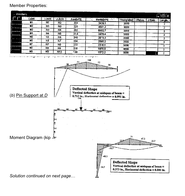
(b) Replace the roller at support D in Figure P8.44 by a pin to prevent horizontal displacement
of joint D, and repeat the analysis of the frame. The frame is now an indeterminate structure.
Compare your results with those in part (a), and briefly discuss differences in behavior with
respect to the magnitude of deflections and moments.
NOTE: Because reinforced concrete beams crack due to tensile stresses created by moment
and shear, initial elastic deflections are based on an empirical equation for moment of inertia
established from experimental studies of full-size beams (provided in the ACI Code). This
equation produces an effective moment of inertia I e that varies from about 0.35 to 0.5 of the
moment of inertia I G based on the gross area of the cross section. The additional deflection
due to creep and shrinkage that occurs over time, which can exceed the initial deflection, is
not considered.
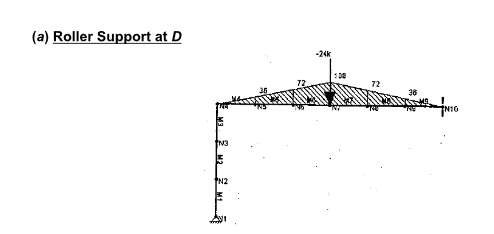
When the support at D is a roller, the horizontal equilibrium of the entire structure requires
that the reaction at support A (i.e., the shear of column AB) be equal to zero, As a result,
column AB is subjected to an axial load only and beam BD acts as a simply supported beam.
Since end B of the beam rotates, column AB has to sway to the right in order to maintain the
90-degreee angle with the beam and, at the same time, the column has to remain straight
(i.e., no moment in the column.) Once the roller is replaced by a pin support, the horizontal
reaction at A produces a moment at the top end of the column, which restrains the beam and
reduces the vertical deflection at midspan by about a half; this restraining effect also reduces
the beam moment at midspan by 34%.
You might also like to view...
Are there any general notes shown on the drawing?
Review drawing number 522923A0A and then answer the following questions.
As of July 1, 1992, it is illegal to intentionally vent ____ refrigerants into the atmosphere.
A. CFC B. HCFC C. Polyvinylether (PVE) D. Both a and b.
All electrical equipment and conductors are to be considered ____________________ until determined to be otherwise by testing methods.
Fill in the blank(s) with the appropriate word(s).
Why do you have to discard the emery board after used?
What will be an ideal response?