The automatic control system for the temperature of a bath of liquid consists of a reference voltage fed into a differential amplifier. This is connected to a relay, which then switches on or off the electrical power to a heater in the liquid. Negative feedback is provided by a measurement system, which feeds a voltage into the differential amplifier. Sketch a block diagram of the system and explain how the error signal is produced.
What will be an ideal response?
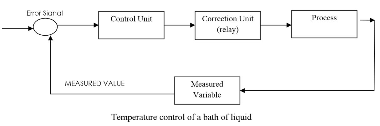
Controlled variable = temperature of the bath of liquid
Reference value= required liquid temperature
Error signal= difference between measured & required temp.
Correction unit= regulator and relay
Process = heating
Measuring device = temperature sensor
You might also like to view...
When rigging a load, the center of gravity must be _____ the hook.
a. at least six inches above b. at least one inch above c. even with d. below
Bottles filled by a certain machine are supposed to contain 12 oz of liquid. In fact the fill volume is random with mean 12.01 oz and standard deviation 0.2 oz.
a. What is the probability that the mean volume of a random sample of 144 bottles is less than 12 oz? b. If the population mean fill volume is increased to 12.03 oz, what is the probability that the mean volume of a sample of size 144 will be less than 12 oz?
How is ultrasound used in leak detection?
A) It makes exiting gasses visible. B) It allows for a visual close-up of the system. C) It amplifies the sound of a leakage. D) It causes the formation of bubbles near a leak.
Problem 1.C6
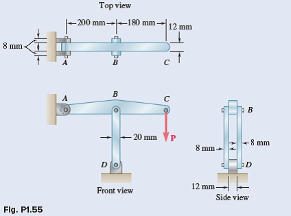
Member ABC is supported by a pin and bracket at A, and by two links that are pin-connected to the member at B and to a fixed sup¬port at D. (a) Write a computer program to calculate the allowable load Pall for any given values of (i) the diameter d1 of the pin at A, (ii) the common diameter d2 of the pins at B and D, (iii) the ultimate normal stress ?U in each of the two links, (iv) the ultimate shearing stress ?U in each of the three pins, and (v) the desired overall factor of safety F.S. (b) Your program should also indicate which of the following three stresses is critical: the normal stress in the links, the shearing stress in the pin at A, or the shearing stress in the pins at B and D. (c) Check your program by using the data of Probs. 1.55 and 1.56, respectively, and comparing the answers obtained for Pall with those given in the text. (d) Use your program to determine the allowable load Pall, as well as which of the stresses is critical, when d1 = d2 = 15 mm, ?U = 110 MPa for aluminum links, ?U = 100 MPa for steel pins, and F.S. = 3.2.
Problem 1.56
In an alternative design for the structure of Prob. 1.55, a pin of 10-mm diameter is to be used at A. Assuming that all other specifi¬cations remain unchanged, determine the allowable load P if an over¬all factor of safety of 3.0 is desired.
Problem 1.55
In the structure shown, an 8-mm-diameter pin is used at A, and 12-mm-diameter pins are used at B and D. Knowing that the ultimate shearing stress is 100 MPa at all connections and that the ultimate normal stress is 250 MPa in each of the two links joining B and D, determine the allowable load P if an overall factor of safety of 3.0 is desired.