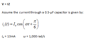
The generalized version of Ohm’s law for impedance elements is:
a. Express the source current in phasor notation.
b. Determine the impedance of the capacitor.
c. Determine the voltage across the capacitor, in phasor notation.
Analysis:
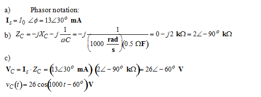
Note that conversion from phasor notation to time notation or vice versa can be done at any time.
You might also like to view...
Employees should use extreme caution when working on scaffolds during high winds.
Answer the following statement true (T) or false (F)
Contrary to popular belief, DR strategies go substantially beyond the recovery portion of data backup and recovery. Discuss what further steps are necessary.
What will be an ideal response?
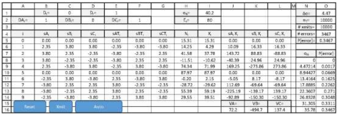
Error correction using three FDMA orthogonal signals. The following worksheet specifies three 10- sample FDMA orthogonal data signals: sA1 in B5:B14, sB1 in C5:C14 and sC1 in D5:D14. Random transmitted bit Dt is computed in C1. The transmitted signal sATi (in E5:E14) = sAi if Dt=1 and =-sAi if Dt=0. The transmitted signal sBTi (in F5:F14) = sBi if Dt=1 and =-sBi if Dt=0. The transmitted signal sCTi (in G5:G14) = sCi if Dt=1 and =-sBi if Dt=0. The Gaussian noise sequence Ni SD ?N is specified in I1. The detected signal Xi is computed as the sum of the three signals and noise in I5:I14. The matched processor component sAiXi is computed in J5:J14 and VA is computed in J16. The matched processor component sBiXi is computed in K5:K14 and VB is computed in K16. The matched processor
component sCiXi is computed in L5:L14 and VC is computed in L16. The detected bit DAr is computed in B2 from VA, DBr is computed in D2 from VB, and DCr is computed in F2 from VC. The received data bit Dr in E2 is computed using error correction applied to DAr , DBr and DCr
The probability of error is estimated by computing the ratio of errors to transmitted data in O5 as the noise ?N varies from 0 in steps of ?? = (Es/2)1/2 using Es computed in I2. The total number of data bits to be transmitted nT is specified in O2. The number of transmissions accomplished in shown in O3 – with 1 bit per three-signal transmission - and the number of errors in O4. Three VBA Macros are present:
The probability of error is estimated by computing the ratio of errors to transmitted data in O5
as the noise ?N varies from 0 in steps of ?? = (Es/2)1/2 using Es computed in I2. The total number
of data bits to be transmitted nT is specified in O2. The number of transmissions accomplished in
shown in O3 – with 1 bit per three-signal transmission - and the number of errors in O4. Three
VBA Macros are present:
? ResetEC resets the counts in O3 and O4.
? XmitEC increments the number of transmissions by one for each signal transmission
and, if an error occurs (Dr ? Dt) increments the error count.
? AutoEC computes the P[error] for nT transmissions as ?N varies and displays the results
in N8:O16.
a. What is the formula in C1?
b. What is the formula in E10?
c. What is the formula in F10?
d. What is the formula in G10?
e. What is the formula in H10?
f. What is the formula in I10?
g. What is the formula in K10?
h. What is the formula in K16?
i. What is the formula in B2?
j. What is the formula in D2?
k. What is the formula in F2?
l. What is the formula in E1?
m. What is the formula in 01?
n. What is the formula in O5?
o. Compose ResetEC.
p. Compose XmitEC.
q. Compose AutoEC.
K, the constant used for lot sizing, is calculated as the:
A) sum of the square roots of demand divided by the number of orders per year. B) order point minus safety stock. C) annual demand divided by the order quantity. D) standard deviation of the demand divided by the square root of demand. E) reciprocal of order quantity times the economic order quantity.