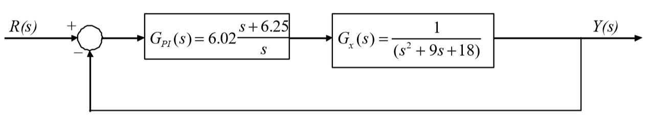
Design a PI controller using root locus techniques for the plant
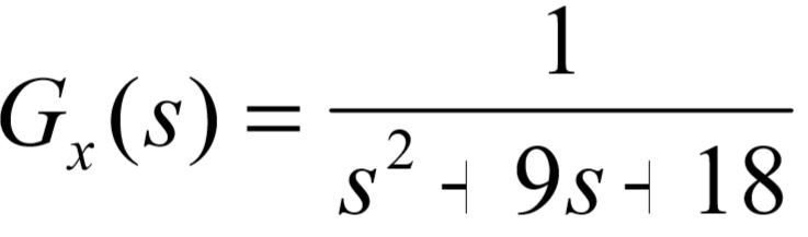
such that the following performance specifications are met.
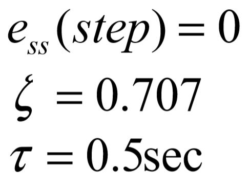
System is stable.
What will be an ideal response?
Step 1:
The steady state step error spec is satisfied by the pole of the PI compensator which makes the control system a type 1 system.
Step 2:
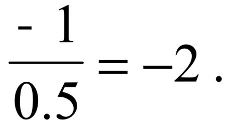
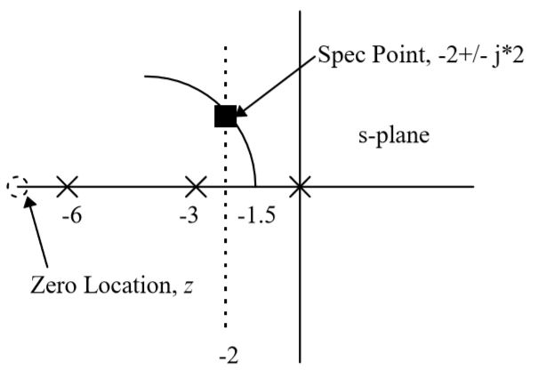
In this step we will design the PI zero and the K for desired closed loop pole locations. A root locus sketch is necessary. The following figure presents the PZ plot for the control system 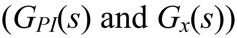 and the performance specification which is just a time constant. This time constant value, 0.5, identifies a pole location at
 The root locus
sketch is shown below,
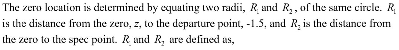


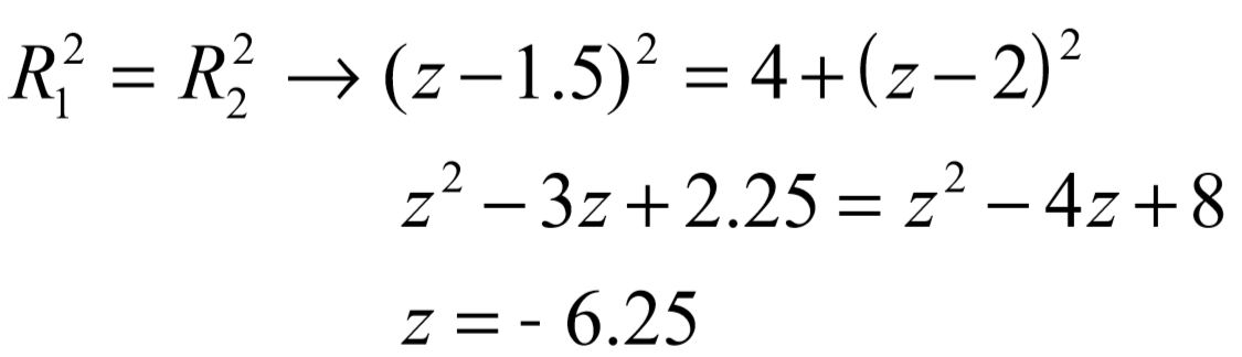
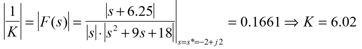
To find the gain value, we simply solve the root locus magnitude condition at s*. This calculation is performed below.
This compensator is implemented in the cascade configuration shown in the following figure.
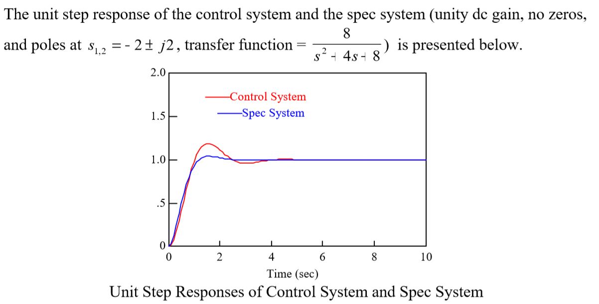
The slight difference between the two responses is due to the interaction of the plant pole located at -6.
You might also like to view...
The expansion valve in an A/C system converts the high-pressure liquid into a:
A. low-pressure liquid. B. low-pressure vapor. C. high-pressure liquid. D. high-pressure vapor.
List the four compartments of the ruminant stomach and explain the function of each
What will be an ideal response?
Recipes are used to construct the nonsinusoidal waveform. What is this process called?
A. Harmonics B. Calculations C. Synthesis D. Analysis
How many ways can an arc be tangent to one line? To two lines? To a line and an arc? To two arcs? Draw examples of each
What will be an ideal response?