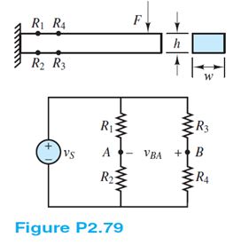
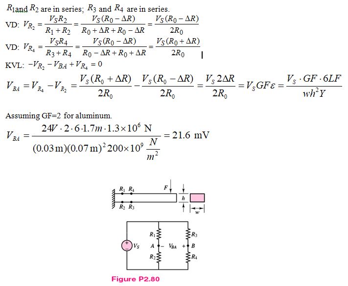
Refer to Figure P2.79 but assume that the cantilevered beam loaded by a force F is made of steel. Strain gauges R1, R2, R3, and R4 are attached to the beam and connected in the circuit shown. The force causes a tension stress on the top of the beam that causes the length (and therefore the resistance) of R1 and R4 to increase and a compression stress on the bottom of the beam that causes the length (and therefore the resistance) of R2 and R3 to decrease. The result is a voltage vBA across nodes B and A.
Determine this voltage if F = 1.3 MN and
Ro = 1k? vS =24V L = 1.7 m
w = 3 mm h = 7 cm Y = 200 GN/m2
Known quantities:
Schematic of the circuit and geometry of the beam shown in Figure P2.79, characteristics of the material, reads on the bridge.
Find:
The force applied on the beam.
Assumptions:
Gage Factor for Strain gauge is 2
Analysis:
You might also like to view...
Can clinical sinks be used as a substitute for service sinks?
What will be an ideal response?
Which diesel system supplies high-pressure diesel fuel to all of the injectors all of the time?
A) Distributor B) Inline C) Rotary D) High pressure common rail
What are internal marketing strategies selected to achieve?
What will be an ideal response?
Opening a drain or blowdown valve on an operating boiler can result in _____
a. boiler damage b. flash steam c. a rise in boiler operating pressure d. valve failure