How are the overload contacts connected in the logic circuit described in this chapter?
What will be an ideal response?
The normally closed overload contacts for starters 1M and 2M are connected in series with the appropriate starter. It is common practice by many industries to leave the overload contacts hard wired to the starter coil to ensure that the starter will de-energize in the event of an overload. Some manufacturers of motor control equipment provide a second overload contact that is normally open. This contact can be used as an input to the PLC and placed in the logic of the circuit. In this example, however, it is assumed that the overload relay contains a single normally closed contact that will remain hard wired to the coil. The common output terminal is connected to the hot or ungrounded power conductor and the other side of each coil is connected to the neutral or grounded power conductor.
You might also like to view...
Joist hangers are steel connectors
A) that connect floor joists with a supporting beam. B) that connect floor joists with floor sheathing. C) that connect floor joists with the supporting wall. D) all of the above.
During one stroke in a four-cycle engine, the crankshaft revolves how many degrees?
A) 180 B) 240 C) 720 D) 360
For the circuit in Fig. 4.109, find the Thevenin equivalent between terminals a and b.
 - LibreOffice Writer.png)
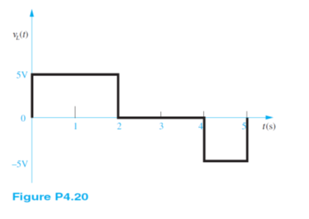
The voltage vL (t) across a 10-mH inductor is shown in Figure P4.20. Find the current iL (t) through the inductor. Assume iL (0) = 0A.