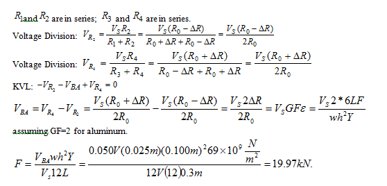
Figure P2.79 shows an aluminum cantilevered beam loaded by the force F. Strain gauges R1, R2, R3, and R4 are attached to the beam as shown in Figure P2.79 and connected into the circuit shown. The force causes a tension stress on the top of the beam that causes the length (and therefore the resistance) of R1 and R4 to increase and a compression stress on the bottom of the beam that causes the length (and therefore the resistance) of R2 and R3 to decrease. The result is a voltage of 50 mV at node B with respect to node A. Determine the force if
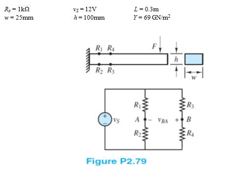
Find:
The force applied on the beam.
Assumptions:
Gage Factor for Strain gauge is 2
Analysis:
You might also like to view...
One free energy monitoring tool that enables a consumer to view home energy consumption from anywhere online using information provided by monitoring systems like the TED 5000, utility smart meters, or other energy monitoring devices is the ____________________.
Fill in the blank(s) with the appropriate word(s).
In overdrive, the direct clutch drives the planetary carrier counterclockwise, causing the long pinions to walk counterclockwise around the held large sun gear.
Answer the following statement true (T) or false (F)
Which of the following are the same as general-use snap switches?
a. Snap switches b. Toggle switches c. Switches d. All of the above
What should be regarded as the maximum allowable stroke for a standard type 30, clamp-type brake chamber?
A. 2" B. 1 3/4" C. 2 1/4" D. 8 3/32"