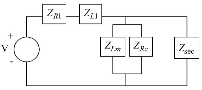
A transformer circuit which accounts for magnetization and core losses is presented in the following figure.
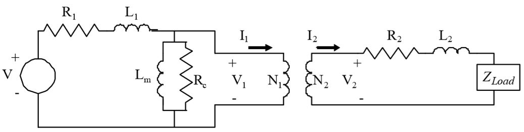
Voltage, Vin, is applied to the transformer primary side coil which consists of a series resistance and inductance, R1 and L1. The secondary side coil of the transformer is also modeled as a series resistance and inductance, R2 and L2. The magnetization and core losses in the core of the transformer are modeled with Lc and Rm. The impedance diagram for the transformer is created by replacing each element of the circuit with its associated impedance. The impedance of each resistance, Ri, is denoted as ZRi, and the impedance of each inductance, Li, as ZLi.
Draw the impedance diagram for the transformer system.
Draw the block diagram from the impedance diagram
From the block diagram compute the system equation relating the input, Vin, to the output, I2.
What will be an ideal response?
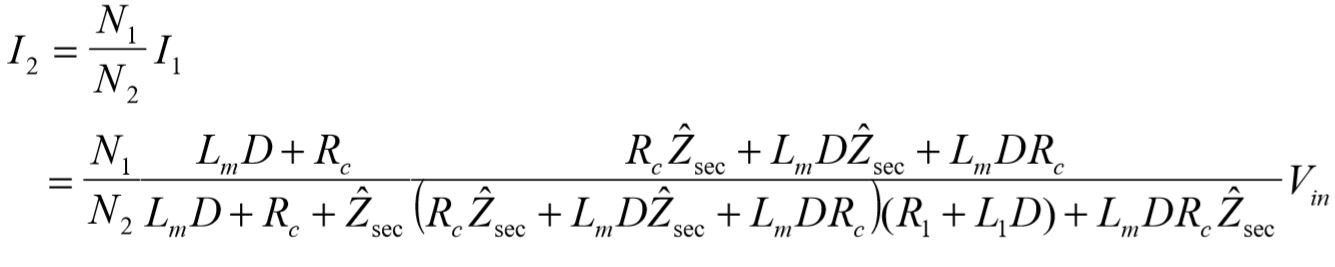
The approach used to solve for the system equations will be to first reflect the secondary side of the transformer to the primary side, compute the primary current, and finally compute the secondary current using the transformer relationship for current: 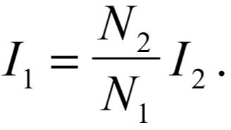
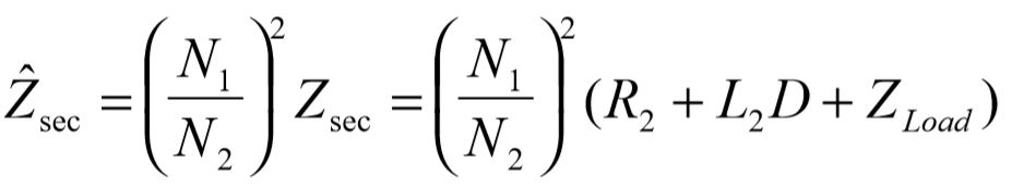
The entire secondary side consists of three series impedances which can be combined into a single secondary impedance,  The combined secondary impedance can be reflected to the primary side of the transformer by multiplying it by the inverse of the winding ratio squared. This is readily verified beginning with the transformer equations:
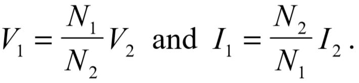
The sign is reversed on the current due to its orientation in this example. Solving for the primary impedance 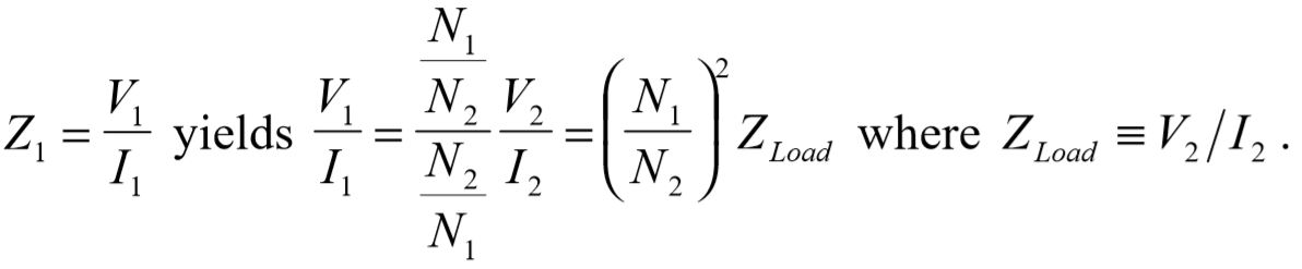
The load impedance as seen from the primary side of the transformer is therefore modified by the square of the winding ratio: 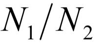 . In the opposite direction, had a load been attached to the primary coil, the impedance as seen from the secondary side would be modified by the square of the reciprocal of the winding ratio.
The reflected combined secondary impedance becomes:
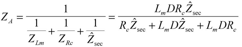
At this point the partially reduced impedance diagram reduces to:
The three parallel impedances are reduced using the parallel law to single impedance denoted as ZA,
Next the total input current drawn is computed using Ohm's law:
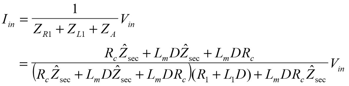
The actual current which makes it to the primary is slightly less than  due to the core loss terms,
  . This current is computed using the flow divider law:
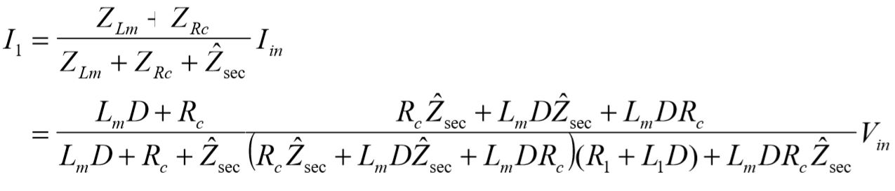
The secondary current becomes:
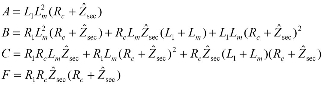
Simplification to monic form results in the following transfer function:
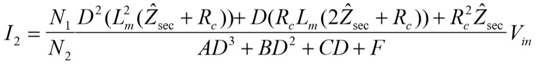
where:
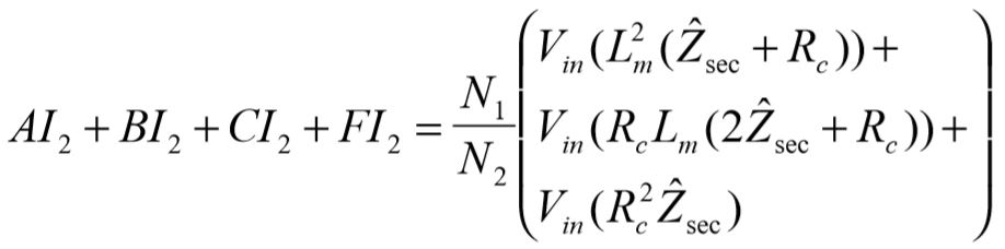
The system equation relating the input,  , to the output,
  , becomes:
Clearly the derivation of the system equation is a formidable task, the reason being the desire to express the output,  , solely as a function of the input,
  .
.
You might also like to view...
A belt marked as an A38 identifies it as a _____.
a. fractional horsepower belt b. classic belt c. wedge belt d. synchronous belt
Technician A says the Chrysler 545RFE is a six-speed transmission. Technician B says that the 545RFE is equipped with two ATF filters, an external canister-type filter, and an oil sump filter. Who is correct?
A. A only B. B only C. Both A and B D. Neither A nor B
What would be the percent horsepower loss while going through the Eisenhower Memorial Tunnel?
Fill in the blank(s) with the appropriate word(s).
____ amplifiers are used as output stages of stereo systems and public address amplifiers, and in many industrial controls.
A. Class A B. Class AB C. Class B D. Class C