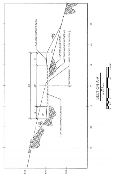
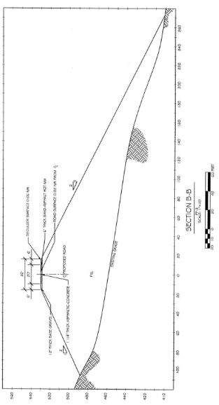
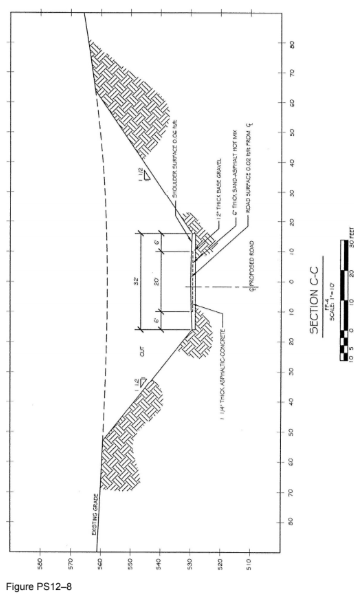
Use the finished drawing from Problem P12–4 to complete this problem. Create three cross sections through the new road and determine the cut and fill. Use the following information for this problem:
Cut three cross sections perpendicular through the road and cut and fill at the
following locations: cross section A, 220? along the road centerline from point A;
cross section B, 415? from cross section A, or at the widest area of fill; cross
section C, 450? along the road centerline from the PI at point B.
Locate completed cross sections on separate ANSI C size sheets, one section
per sheet.
The vertical scale of the cross sections is to be the same as the horizontal scale.
The road surface has a slope of 0.02 ft./ft. from the road centerline.
The shoulder surface has a slope of 0.06 ft./ft. from the edge of pavement (EOP).
Exaggerate the road and shoulder surface slope angle on the drawing for clarity.
The road has the following composition: 12?? thick base of gravel (show as
dashed line); 6?? thick sand–asphalt hot mix (show as solid line); 1 1/4?? thick
asphaltic–concrete surface (show as thick solid line).
Draw cross sections with an appropriate scale that allows the drawing, especially
the area of cut and fill, to be shown as large as possible on the sheet. Each cross
section sheet may have a different scale.
Label the centerline of the proposed road, bearings and distances, and location
points on the road.
Label the road width, shoulder width, road surface and shoulder surface slopes,
and the centerline of the road in all cross sections.
Label the road composition in all cross sections as local notes or called out on
one sheet in general notes, with local note references on each drawing.
Indicate cut and fill in cross sections with a note and show the angle of repose
symbol and values on each side of the road, along the appropriate slope.
Below all three cross section viewing arrow symbols on the base drawing, place
a drawing reference in parentheses. For example, section A-A, if shown on sheet
number P12–8–02, should have the label (P12–8–02) below one of the viewing
arrows. Place a similar cross-reference label on the cross section drawing just
below the section name.
Use an appropriate graphic pattern to indicate areas of undisturbed Earth only.
Place patches of this symbol at angular changes of undisturbed Earth and
several places along slopes.
Title all cross section drawings HWY. CROSS SECTION.
Change the title of original map to HIGHWAY CUT AND FILL.
Begin drawing numbers with P12–8–01 on the HIGHWAY CUT AND FILL
drawing and continue in sequence with cross sections.
Label the sheets as a set, such as 1 of 4, 2 of 4, and so on.
Submit drawings plotted to scale on ANSI C size sheets, complete with border
and title block.
See Figure PS12–8.
You might also like to view...
The simplest section view is the ____.
A. viewing direction B. cutting plane C. full section D. half section
The size of a fillet weld is shown on the ____ side of the reference line as (to) the weld symbol and to the ____ of the symbol.
A. other; left B. same; left C. other; right D. same; right E. none of the above
The resistance reading of an open heating element is:
A) Infinite ohms, which would show OL on most digital meters. B) It is not possible to check the resistance of an open heating element. C) 0, which would show as 0.0 to 0.1 on most digital meters. D) A measurable resistance of approximately 12.
Find the lower limit of a dimension having a bilateral tolerance of ± .015 and an upper limit of 2.562.
What will be an ideal response?