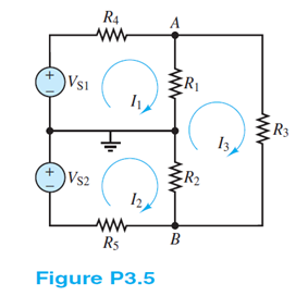
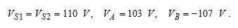
In the circuit shown in Figure P3.5, the source and node voltages are VS1 = VS2 = 110V VA = 103V VB = ?107V Determine the voltage across each of the five resistors.
Known quantities:
Circuit shown in Figure P3.5 with source and node voltages:
Find:
The voltage across each of the five resistors.
Analysis:
Assume a polarity for the voltages across R1 and R2 (e.g., from ground to node A, and from node B to ground). R1 is connected between node A and ground; therefore, the voltage across R1 is equal to this node voltage. R2 is connected between node B and ground; therefore, the voltage across R2 is equal to this voltage.

The two node voltages are with respect to the ground which is given.
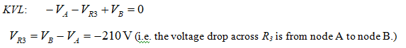
Assume a polarity for the voltage across R3 (e.g., from node B to node A). Then:
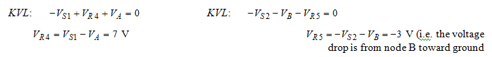
Assume polarities for the voltages across R4 and R5 (e.g., from node A to ground , and from ground to node B):
You might also like to view...
Which of the following best describes virtual fusing?
A. Microprocessor-controlled MOSFET with current feedback B. Magnetic field measurement of over current C. SAE type III manual reset circuit breaker D. PTC circuit protection device
List the veins that may be used for blood collection
What will be an ideal response?
You don't need to prioritize your mail daily, just when there is time
Indicate whether the statement is true or false
Absolute encoder positioning does not require a home position.
Answer the following statement true (T) or false (F)