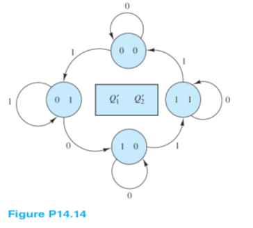
Use JK flip-flops to construct a sequential circuit with the state diagram shown in Figure P14.14.
Analysis:
Notice that there is a single bit input that determines whether the states Q1 Q2 increment (in the sense of a two bit integer) or remain unchanged. When the input bit is low (zero) the output state does not change such that Qn+1 = Qn = 0. In other words, the single bit input acts as an enable input. When the single bit input is high (one) the circuit is enabled and the states Q1 Q2 increment (in the sense of a two bit integer). An AND gate is ideal for creating an ENABLE input. The circuit can be realized as a two bit ripple counter similar to that shown in Figure 14.13. In this problem, only two states exist so the third (right-most) JK flip-flop in Figure 14.13 is not needed. Also, the clock input should be one of two inputs to an AND gate. The other input is the single bit enable input. The output of the AND gate would then be used to trigger the first JK flip-flop.
You might also like to view...
A tire with an A temperature rating has the best temperature resistance.
Answer the following statement true (T) or false (F)
What does the acronym USGBC stand for?
What will be an ideal response?
The two-piece master cylinder body is usually made of ____________________.
Fill in the blank(s) with the appropriate word(s).
The overload device mounted in the compressor terminal box would be classified as a ____.
A. safety control B. capacitor C. pressure control D. speed control