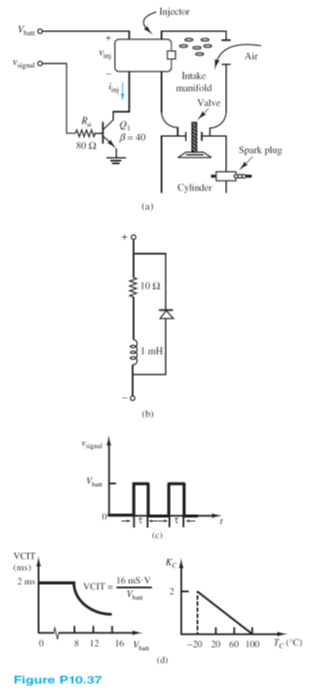
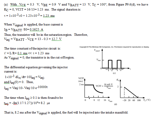
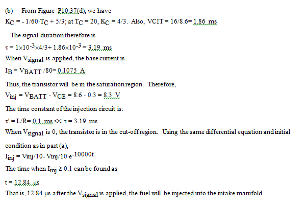
An automobile fuel injector system is depicted in Figure P10.37(a). The internal circuitry of the injector can be modeled as shown in Figure P10.37(b). The injector will inject gasoline into the intake manifold when Iinj ? 0.1 A. A voltage pulse train vsignal is shown in Figure P10.37(c). For a cold engine at start-up, the pulse width ? is determined by:
? = BIT × KC + VCIT where
BIT = basic injection time = 1 ms
KC = compensation constant of temperature of coolant (TC )
VCIT = voltage-compensated injection time
The characteristics of VCIT and KC are shown in Figure P10.37(d). Assume the transistor Q1 saturates at VCE = 0.3 V and VBE = 0.9 V. Find the period of the fuel injector pulse if:
a. Vbatt = 13 V, TC = 100°C
b. Vbatt = 8.6 V, TC = 20°C
You might also like to view...
Referring to the following figure, closing all four switches at the same time would cause ____ at the A/D input referenced to ground.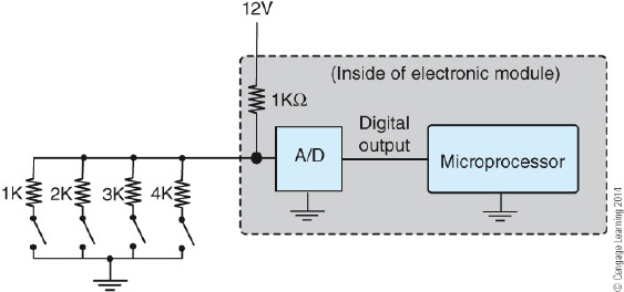
A. more than 6V B. 12V C. less than 6V D. more than 8V
What is the value of X in the table below?
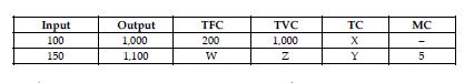
A) 1,200
B) 1,000
C) 200
D) Cannot say; insufficient information
What electrical rating on the unit data plate is useful for sizing the circuit breaker for the unit?
What will be an ideal response?
Where are cascade systems primarily used?
A. extra-low temperature range B. low temperature range C. medium and low temperature ranges D. medium temperature range