1. A walk-in freezer using R404A has the following conditions. Which of the groups of choices is the most logical explanation for the problem?
? Box temperature 30°
? Suction pressure 20 psig LOW Evaporator temperature (-15°)
? Suction line leaving the evaporator is 20° HIGH Superheat (35°)
? Ambient temperature is 70°
? Head pressure is 190 psig LOW (85° condensing temp means 15° condenser split)
? The liquid line is 75°. NORMAL subcooling (10°)
a. The unit is low on refrigerant or the ambient is too cold.
b. There is a restriction in the liquid line or the expansion valve.
c. The head pressure control is not operating on the condenser.
d. The evaporator is dirty, iced up, or there is an evaporator fan problem.
b. There is a restriction in the liquid line or the expansion valve.
You might also like to view...
Jose has 460 acres of cotton. For weed control, he treated the soil with 1.75 pints of herbicide per acre at $105 per 2.5-gallon container. He applied 180-86-148 units of fertilizer per acre using 46-0-0 urea at $510 per ton, 18-46-0 DAP at $710 per ton, and 0-0-60 muriate of potash at $572 per ton. What was the total cost of the herbicide and fertilizer?
What will be an ideal response?
____ control systems were used before electronics.
A. Pneumatic B. Manual C. Digital D. Mechanical
The primary holding power of a vacuum chuck is:
A) Suction negative pressure B) Hydraulic pressure C) Atmospheric pressure on the workpiece D) Vacu-magnetism
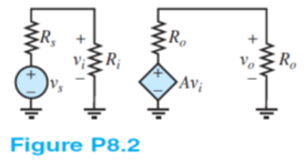
A temperature sensor in a production line under normal operating conditions produces a no-load (i.e., sensor current = 0) voltage:
vs = Vpk cos(?t) Rs = 400?
Vpk = 500mV ? = 6.28 krad/s
The temperature is monitored on a display (the load) with a vertical line of light-emitting diodes. Normal conditions are indicated when a string of the bottommost diodes 2 cm in length is on. This requires that a voltage be supplied to the display input terminals where
Ro = 12 k? vo = Vm cos(?t) Vm = 6V
The signal from the sensor must be amplified. Therefore, a voltage amplifier, shown in Figure P8.2, is connected between the sensor and CRT with
Ri = 2k? Ro = 3k?
Determine the required no-load gain of the amplifier.