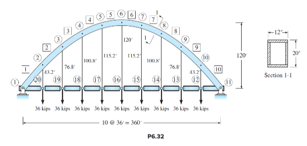
Computer study of a two-hinged arch. The objective is to establish the difference in response of a parabolic arch to (1) uniformly distributed loads and (2) a single concentrated load.
(a) The arch in Figure P6.32 supports a roadway consisting of simply supported beams
connected to the arch by high-strength cables with area A = 2 in. 2 and E = 26,000 ksi. (Each
cable transmits a dead load from the beams of 36 kips to the arch.) Determine the reactions,
the axial force, shear, and moment at each joint of the arch, and the joint displacements. Plot
the deflected shape. Represent the arch by a series of straight segments between joints. The
arch has a constant cross section with
A = 24 in. 2 , I = 2654 in. 4 , and E = 29,000 ksi.
(b) Repeat the analysis of the arch if a single 48-kip vertical load acts downward at joint 18.
Again, determine all the forces acting at each joint of the arch, the joint displacements, etc.,
and compare results with those in (a). Briefly describe the difference in behavior.
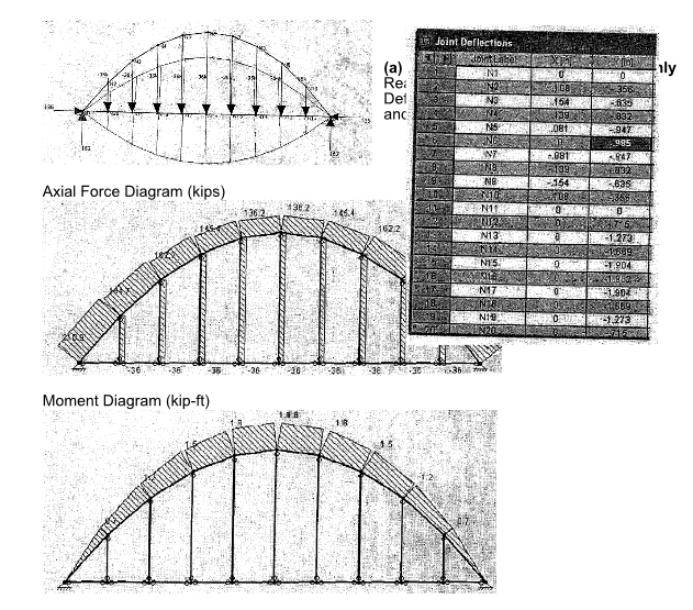
Observation:
A continuous uniformly distributed load, acting on a parabolic arch will produce a resultant
axial compression force acting at the centroid of all cross sections. While the axial force, and
the direct stresses it produces, will shorten the arch, the changes in length of the arch axis
and the vertical deflection of points along the arch axis will typically be small if the magnitude
of the direct stresses are in the elastic range of the material. In the case of the arch in Fig.
P7.16, the nine equally spaced loads of 36 kips approximate a uniformly distributed load that
will produce a uniform compressive stress on all cross sections of the arch (see the plot of
axial forces and moments on page 6.32B.
The magnitude of joint deflections is listed in the table on page 6.32A. At the level of the
bridge deck, the vertical deflection of the floor system will vary with the length of the cable. In
practice, the deflection of the floor system due to the dead weight of the bridge can be
eliminated by shortening the length of the vertical cables that support the floor system (joints
12 to 20). This will eliminate the appearance of a sagging roadway. For example, if the
vertical deflections of the floor system at joints 12 through 20 produced by the 36 kip loads is
to be eliminated, the cables can be shortened by the displacements tabulated in column Y in
the table of joint deflections on
Page 6.32A. These directions range from approximately 3/4 inches near the supports to
nearly 2 inches at midspan where the cables are longest.
(b) Uniformly distributed dead load + 48-kip live load
Reactions (kips),
Deflections (in),
and Deflected Shape
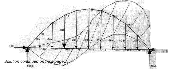
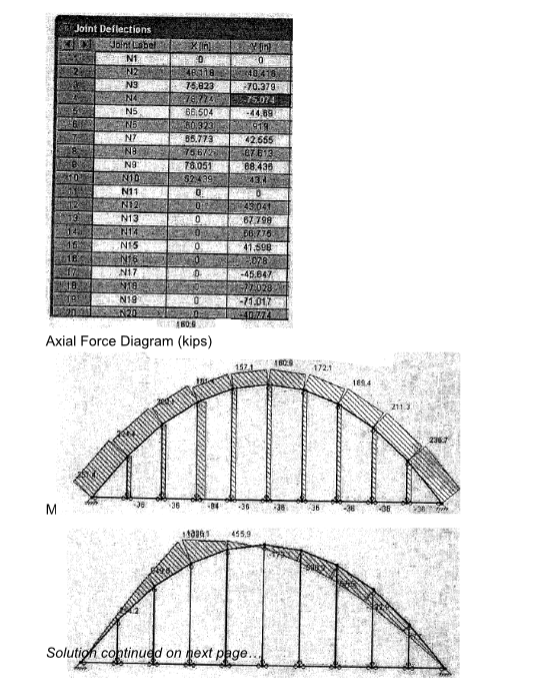
The addition of the 48-kip concentrated load at joint 18 will produce large values of bending
moment in the arch and large deflections (Over 6 feet at some joints) in both the vertical and
horizontal directions. Such large deflections are obviously not acceptable and would result in
damage to the bridge and its deck as well as produce discomfort for people driving over the
excessively flexible bridge. To reduce deflections, the designer has several choices:
1. A deep continuous bridge girder can be used (see Fig. P6.32). The effect of a deep stiff
continuous girder is to spread the concentrated load longitudinally to adjacent vertical cables,
thereby applying a more uniformly distributed load to the arch. The effectiveness of this
strengthening scheme is demonstrated in P6.32.
2. The arch can be stiffened by incorporating a truss. See, for example, page 240 of the
textbook; the highway bridge is composed of an arch, which also forms the lower chord of a
truss composed of diagonal members and the girders of the roadway. The arch carries most
of the dead load and the deep, stiff trussed-arch carries most of the forces produced by the
vehicles passing over the bridge. The Bayonne Bridge, one of the longest in the world, is also
stiffened by a truss
You might also like to view...
To lay out stairs, use thick lines placed with the LINE.
Answer the following statement true (T) or false (F)
Payoff matrix is useful when the decision-making conditions have an element of risk such
that the probability of occurrence of each outcome cannot be estimated
Indicate whether the statement is true or false.Being cooled by a fan moving room-temperature air across the body is an example of cooling by:
A) Conduction. B) Convection. C) Radiation. D) Evaporation.
Factors that affect kerf width are:
A) Incorrect settings B) Travel speed C) Excessive gas flow rates D) All of the above