PROBLEM 2.8
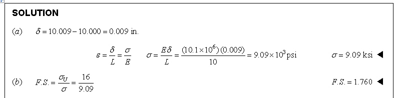
Two gage marks are placed exactly 10 in. apart on a 1/2 -in.-diameter aluminum rod with E = 10.1 ? 106 psi and an ultimate strength of 16 ksi. Knowing that the distance between the gage marks is 10.009 in. after a load is applied, determine (a) the stress in the rod, (b) the factor of safety.
You might also like to view...
In a typical fuel subsystem, which of the following is capable of entrapping the smallest particles suspended in the fuel?
A. primary filter B. fuel/ water separator C. pre-strainer D. secondary filter
The abbreviation for an entrance ell (elbow) is _____.
a. SLB b. ELLB c. EE d. IEEE
Organic matter comes from _____ sources
A) mineral B) parent C) living D) rock
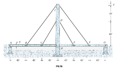
Computer study of a cable-stayed bridge. The deck and tower making up the two-span, cable-stayed bridge in Figure P6.16 are constructed of reinforced concrete. The cross section of the bridge is constant with an area of 15 ft 2 and a moment of inertia of 19 ft4. The dead weight of the girders is 4 kips/ft. In addition the girders are to be designed to support a live load of 0.6 kips/ft that is to be positioned to maximize the design forces in individual members. The vertical cable tower, located at the center support, has a cross-sectional area of 24 ft2 and a moment of inertia of 128 ft 4 . Four cables, each with an area of 13 in. 2 and an effective modulus of elasticity of 26,000 kips/in. 2 , are used to support the deck at the third points of each 120 ft span. The modulus of elasticity
of the concrete is 5000 kips/in. 2 . The cable reaction may be assumed to be applied to the underside of the roadway. Members have been detailed such that the support at D acts as a simple support for both the tower and the roadway girders.
(a) Analyze the structure for full live and dead loads on both spans, that is, establish the shear, moment, and axial load diagrams for the girders, the forces in the cables, and the maximum deflection of the girders.
(b) With the dead load on both spans and the live load on the left span ABCD, determine the shear, moment, and axial load diagrams for both spans, the axial force in the cables, and the shear, moment, and axial load in the vertical cable tower. Also determine the lateral deflection of the cable tower.