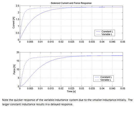
With reference to Example 18.11, generate a simulation program (e.g., using SimulinkTM) that accounts for the fact that the solenoid inductance is not constant but is a function of plunger position. Compare graphically the current and force step responses of the constant-L simplified solenoid model to the step responses obtained in Example 18.11. Assume ?r = 1,000.
Example 18.11
Analyze the current response of the solenoid of Example 18.10 to a step change in excitation voltage. Plot the force and current as a function of time.
Example 18.10
Figure 18.40 depicts a simplified representation of a solenoid. The restoring force for the plunger is provided by a spring.
1. Derive a general expression for the force exerted on the plunger as a function of the plunger position x.
2. Determine the mmf required to pull the plunger to its end position (x = a).
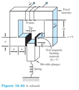
Assumptions:
The reluctance of the iron is negligible, Neglect fringing Neglect damping on the plunger
.png)
You might also like to view...
Water supply lines are ____ and gas lines are ____.
A. pressurized; pressurized B. pressurized; unpressurized C. unpressurized; pressurized D. unpressurized; unpressurized
An object is sketched in isometric by positioning it so that the part seems to rest on ____.
A. the front face B. one corner C. the back face D. its top
Which is TRUE of a fixed caliper?
A) Simple construction B) Inexpensive to manufacture C) Compact in size D) Flexes less than other designs
When the oil pressure drops to between 3 and 7 psi, the oil pressure lamp lights by ________
A) Conducting current to dash lamp by oil B) Opening the circuit C) Grounding the circuit D) Shorting the circuit